Reading temperatures & controlling a fan with a RP2, Azure Service Bus and a Microsoft Band (1)
Part 1 - Idea, architecture, hardware shopping list and hardware configuration
Sometimes simple ideas have a tendency to balloon almost out of control, and this is one of them. In essence I wanted 'the other way around' compared with my previous IoT project - in stead of using the Band as a sensor device and the Raspberry PI2 as a 'display unit', I wanted to use the Band as controller. The idea was I could
- Measure temperature using my Raspberry PI2 running Windows 10 CoreIoT
- See the current temperature on my Band, including the date and time it was measured
- Send a command to my Raspberry PI2 to switch on a fan if I find things are getting too hot
- See on my Band the fan has actually switched on
- Switch the fan off again if I feel like doing so.
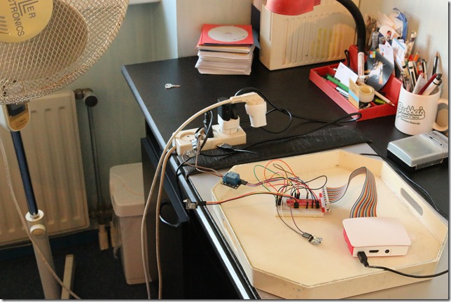
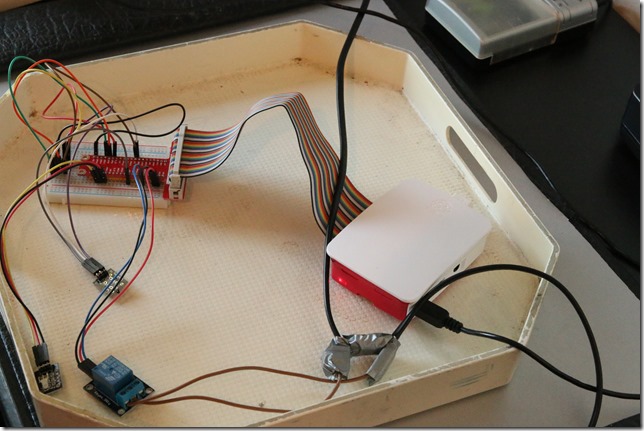
Some pictures of the resulting contraption on my desk:
I will say you this my friends: playing around with IoT stuff takes the phrase "spaghetti code" to a whole new level :DThe details
On my phone (or more precisely, the Windows 10 device to which my Band is paired) there is an app than can
- listen to temperature data coming from the Raspberry PI2,
- build a tile with a custom UI on my Band,
- listen to and act on events coming from that Band UI.
If I open the custom tile on my Band, the app on my phone gets a signal to transmit the last received data from my Raspberry PI2 (the temperature, last received update date and time, and whether the fan is on or off) to the Band, followed by a single vibrate. If I tap the fan toggle button on the custom UI on my Band, the app should respond to that as well, send back a signal over the Azure Service bus queue - and display on the Band the fan is on (and can now be switched off).
On the Raspberry PI2 is a CoreIoT app that measures temperature and sends data over the Azure Service bus queue every five seconds, and also listens for fan switch on/off commands. It should also display it's 'health' by letting the connected two-color LED flash in green when a correct temperature is measured and transmitted, or red when something goes wrong. I also included a sequence on which the led rapidly blinks red/green to indicated the app is starting up. This is very handy when you set the app to be the default app - that way it's automatically started after the PI2 has booted Windows 10 CoreIoT and you can then see the app is actually starting up, even if there's no display connected.
The net result you can see on this video below:
Thanks to the Azure Service Bus being ‘somewhere’ in the cloud, I can read the temperature in my study on my Band where ever I am in the world. And while that may not be the most useful thing to do, I actually have used this contraption for real when I was on holiday in Germany for the past 1.5 weeks - in stead of a fan, I connected a spotlight to it, enabling me to turn on a light at home at random times in the evening, in order to confuse potential burglars. Like I said,Windows 10 CoreIoT will always try to keep the default app running - after there's a power failure or a crash, it automatically (re)starts that app. A very useful feature when you are hundreds of kilometers from home and cannot hit a reboot button.
How this will be blogged
As this is quite a big project, I have decided to split the explanation into six blog posts:
- Idea, architecture, hardware shopping list and hardware configuration
- Using an Azure Service Bus queue for two-way communication between IoT devices
- Measuring temperatures using an UWP on a Raspberry PI 2
- Controlling a fan using an UWP on a Raspberry PI2 remotely
- A client app to show temperature data and control a fan
- A Microsoft Band client to read temperatures and control a fan
The idea I just described, so now we go on with the architecture
Architecture
For my previous IoT project - displaying heart rates using an LED connected to a Raspberry PI2 - you might recall I used an Azure hosted Signal/R Hub. This time, as I already said, I decided to go with a queue on an Azure Service Bus. Signal/R worked pretty well in the previous setup, but it has a few disadvantages:
- It requires you to deploy a web site, while the infrastructure for a Service Bus is 'hosted' by Azure itself.
- Signal/R signals can only be delivered real time - that is the nature of Signal/R. If you missed it, you missed it. Tough boots. A queue makes it possible to receive data for a little while after it's been sent.
- Security is a bit iffy - everyone who knows the address of my previous Signal/R hub solution can listen in on the data. Of course, I can encrypt that, or do access security - it's all kind of a hassle and it feels a bit roll-your-own.
There is also a disadvantage - unlike with Signal/R, there is basically only one client possible - that is the nature of a queue. If a client picks up the message, it's removed from the queue. A second client listening won't get it. So a 'broadcast' scenario is not possible. But since this is exactly what I wanted, this suited me perfectly. And my good friend Matteo Pagani from Italy had played with if before, and was kind enough to provide me with some starter code so I could go off to a flying start.
This is a high level overview of the setup: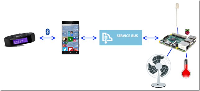 Calling this 'architecture' is a bit rich I think, but it is intended as a global overview. Although it is not entirely correct, as this picture suggest signals go between phone and PI2 (and back) over a single channel, while in fact there are two queues - one for each direction. Temperature data goes from PI2 to phone over one queue, the command to toggle the fan over the other.
Contrary to most of my demo solutions, this is a more architected solution. It uses separate components connected by dependency injection, and the Windows 10 (mobile) client is a fully fledged MVVMLight app. This is because I wanted to show a little more of how to do things in a more robustly architected way. It also makes it easier to split the blog post into manageable pieces. This is not just a simple demo - it's a complete setup.
The demo solution contains the following projects:
- TemperatureReader - the CoreIoT UWP app running on a Raspberry PI2 that actually reads the temperature data and displays it on a screen - if one is attached, sends data over the Service Bus and waits for commands to switch the fan on or off. Or actually, just the very limited UI that bootstraps the whole process - all the logic is in
- TemperatureReader.Logic - contains all of the logic of reading temperature, flashing the LED and controlling the relay using the GpioController class.
- TemperatureReader.ClientApp is the Windows 10 UWP application that acts as intermediary between the Band and the Raspberry PI2, listening to the signals coming from the PI2 and acting on commands and/or event from the Band. It has it's own user interface to show data and initialize the Band.
- TemperatureReader.ServiceBus code handling communications via the Azure Service Bus.
- TemperatureReader.Shared - contains the data objects that are shuttled over the Service Bus, as well as a global definitions class that defines pins used on the bread board, Azure access keys, and stuff like that - because I don't like magic strings and numbers.
Hardware shopping list
To run this project, you will need the following hardware:
- 1 Raspberry PI2 running the latest Windows 10 CoreIoT build
- 1 Microsoft Band
- 1 device running Windows 10 (mobile or otherwise - as long as a Band can be paired to it)
- 1 Keyes two-color Common-Cathode LED 1
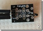
- 1 Keyes Analog-temperature sensor 2
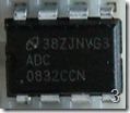
- 1 ADC0832 analog-digital-convertor 3
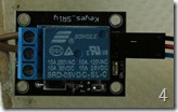
- 1 Keyes SRD-05VDC-SL-C switch 4
- 1 breadboard + flat cable connecting it to the Raspberry PI2
- 14 connection wires (I hope I counted them correct ;) )
- 3 barrier strip units 5 (The things we call ‘kroonsteentjes’ in Dutch)
- 1 piece of mains cord
- 1 mains plug
- 1 mains socket plug
- Some duct tape
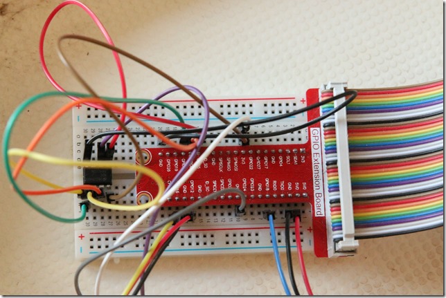
Pictures of some assorted items:
Configuration
A word of warning: the hardware configuration uses a relay switch to control mains power. Depending on where you live, that's between 100 and 250 Volts. We are not talking battery power here - this is the stuff that comes out of your wall plugs, drives the washing machines, refrigerators, air conditioners and whatnot, has serious oomph behind it - and can seriously hurt you if you mess around with it. In my sample I have cut a mains cord, reconnected one part via the relay and reconnected the rest using barrier strips. I sealed the connections using duct tape. At the ends of the mains cord are a mains plug and a main socket, so it can be used to control any mains power driven device. Be sure that you are careful with live wires and be aware that whatever I show you most likely would not get approval from a skilled electrician. If you re-create my setup with your own hardware, I cannot accept any responsibility for things going wrong. I also strongly suggest not letting the setup connected to the mains power unsupervised. This is a test/demo project, not a production unit.
The LED
This is an easy one. I have connected "R" to GPIO12, "Y" to GPIO16, and "G" to GND (of course).
The SRD-05VDC-SL-C switch
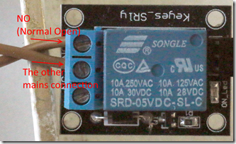
A bit more complicated, as the are no markings on the pins of this device. If you hold it the way that you can read the text on the blue block and the pins are sticking out to the right (as in picture 4) I have connected the top pin to GND, the middle pin to 5V, and the bottom pin to GPIO18.
On the other side, the part with the screws on it - I connected the mains wire. I cut this first, then reconnected to mains using three terminal strip units - an sealed the stuff with duct tape. As already stated - follow this advice at your own risk. Basically one wire goes straight trough, the other part goes through the switch. Now it's not easy to see, but if you hold the switch like displayed on picture 4 (and below), you will see screws on the left side, and you can just about read "NO" under the top screw, and "NC" under the bottom screw. This stands for "Normal Open" and "Normal Closed". You fix one of the mains wire to the NO screw, and the other under the middle screw.
The Analog temperature sensor
I have connected the middle pin to 3.3V, the "-" pin to GND, and "S" pin to 2 of the AC-converter (see below). That converter is the hardest part.
The ADC0832 analog-digital-convertor
I'll be the first one to admit that I actually have no idea how this works, I nicked the idea from the Sunfounders manual. I understand the principle of an A/D converter, I just have no idea why it needs to be connected in this specific way, and I understand even less of the programming 'sequence' (that will be described in a later post) 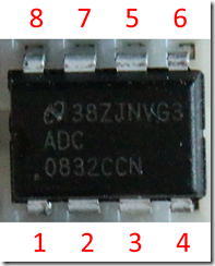 that goes into it. Anyway, this A/D converter is a chip and if you hold it the way that you can actually read the text on it, the pins are numbered this way. Why? I really don't know, having no formal background in electronics. Now this pins also have labels attached to them which are:
1 = CS
2 = CH0
3 = CH1
4 = GND
5 = DI
6 = DO
7 = CLK
8 = VCC
These names we will see back later in the sample solution. So, more or less following lead of the Sunfounders manual, I made the following connections
- 1 to GPIO5
- 2 to the "S" pin of the Analog temperature sensor
- 3 to nothing
- 4 to GND
- 8 to 3.3V
- 7 to GPIO6
- 5 and 6 to GPIO13
Running the sample solution
If you want to run the sample solution, you will at least need to
- Create an Azure Service bus
- Paste the key into Settings.cs in TemperatureReader.Shared
- Deploy the TemperatureReader app on a Raspberry PI2 running Windows 10 CoreIoT with all the named hardware attached
- Deploy the TemperatureReader.ClientApp to a Windows 10 device with a Microsoft Band to it.
The next episode in this series will explain how the Azure Service bus is utilized as an IoT communication conduit.

 MVP Profile
 Try my app HoloATC!
  HoloLens 2
 Magic Leap 2
 Meta Quest
 Android phones
 Snap Spectacles
 Buy me a drink ;)
 BlueSky
 Mastodon
 Discord: LocalJoost#3562
